Introduction
Today, the issue of the safety of buildings and structures from the impact of explosive loads is gaining particular importance due to the growth of terrorist threats, man-made accidents and military conflicts. Designing and surveying structures to ensure their resistance to explosive loads requires deep engineering knowledge and modern technologies.
This article examines the main stages of the survey and design of buildings and structures that may be affected by explosive loads.
1. Risk analysis and inspection of buildings
1.1 Assessment of potential threats
Before starting the design or inspection of structures, it is important to conduct a detailed risk analysis, which includes an assessment of possible sources of explosions (military operations, industrial accidents, terrorist attacks). Possible scenarios of explosions, their intensity and consequences for the building and surrounding infrastructure are evaluated.
1.2 Assessment of the current state of the building
Survey of existing buildings or structures should include the following stages:
– visual inspection of structures (walls, ceilings, foundations);
– measurement of deformations and damages;
– determining the strength of materials;
– assessment of tightness and ability to withstand high loads.
2. Design taking into account explosive loads
2.1 Basic design principles
When designing buildings for resistance to explosive loads, it is important to adhere to the following principles:
Resistance to blast waves: the use of materials capable of withstanding the high pressures and temperatures generated by blasts.
Energy capacity of structures: structures must absorb the energy of the explosion with minimal destruction.
Segmentation of buildings: zoning of buildings to minimize the spread of the blast wave inside the object.
2.2 Use of modern materials
Modern materials such as reinforced concrete, high-strength steel and special blast-resistant coatings can significantly increase the resistance of buildings to explosive loads.
2.3 Modeling of explosive effects
For accurate design, computer modeling is used, which allows simulating explosive processes and their impact on structures. Application of software complexes such as ANSYS, LS-DYNA or ABAQUS allows engineers to evaluate the consequences of different explosion scenarios and optimize the project.
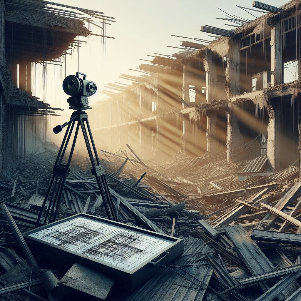
3. Examination after explosions
After explosions, it is important to conduct a quick survey of damaged buildings to assess the extent of destruction and safety for further operation or repair. The main activities include:
– inspection of places of major destruction;
– assessment of residual strength of load-bearing structures;
– proposals for strengthening or dismantling.
4. Increasing the stability of buildings
4.1 Protective barriers and explosion protection
External protective barriers, such as ballistic walls, earth embankments or special blast shields, can significantly reduce the risk of destruction.
Retrofit of existing buildings
To increase the stability of old buildings, it is possible to use retrofit methods, such as:
– strengthening of supporting structures with additional frames;
– installation of explosion-proof windows and doors;
– use of materials that increase hermeticity and resistance to vibrations.
5. Calculation of structures subject to the influence of explosive loads.
Basic aspects of structural calculation
The calculation of building structures that can be subjected to explosive loads has several important features that differ from traditional static and dynamic calculations:
Impulsive nature of the load: explosive loads have a short-term but very intense impact. This creates large peak pressures that must be considered when designing structures.
Velocity of loading: An explosion creates a shock wave that propagates at a velocity much higher than that of normal static loads, so the structure must be able to respond instantaneously to such changes.
Uneven pressure distribution: unlike static loads, explosive loads can act unevenly on individual building elements, so local stress peaks must be taken into account.
5.2 Methods of calculating explosive loads
The calculation of explosive loads is based on a number of parameters that must be taken into account during design:
The mass of the explosive substance (TNT equivalent): this is the main indicator on which the power of the explosion depends. It is used to determine the peak pressures and the duration of the impact of the blast wave.
Distance to the epicenter of the explosion: the farther the building is from the source of the explosion, the less pressure it will feel from the blast wave.
Orientation of the building and its parts in relation to the explosion: the shape of the building and its location can affect the way the blast wave propagates.
5.3 Calculation of strength of structures
The design of explosion-resistant structures requires strength calculations taking into account special factors of explosive loads. The main methods include:
Calculation of peak pressures: The maximum explosion pressure that will act on the surface of the building is determined, and the structure’s ability to withstand this load is calculated.
Formulas include:
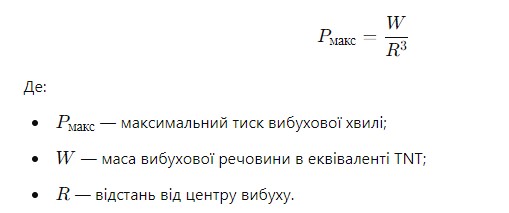
Analysis of impulse strength: in addition to peak loads, it is necessary to calculate the ability of structures to absorb the impulse created by a shock wave.
Analysis of the stability of load-bearing structures: load-bearing elements (columns, beams, slabs) must withstand not only standard loads, but also additional loads that occur during an explosion.
5.4 Methods of dynamic analysis
Dynamic analysis of structures is used to accurately calculate the impact of explosive loads. It allows you to take into account the speed and intensity of the impact of the blast wave on the building. The main methods include:
Modeling in time: numerical methods are used to model the impact of the explosion in the time dimension, which allows to take into account the dynamic effects and oscillations caused by the blast wave.
Finite element method (FEM): allows complex calculations of loads and deformations for each individual element of the structure. This provides an accurate analysis of the impact of blast waves on each element of the building.
5.5 Design taking into account deformations and destruction
When designing, it is important to take into account possible plastic deformations and local destruction that may occur during an explosion. Project documentation should include:
Localization of damage: blast-resistant buildings are designed in such a way as to minimize the spread of damage throughout the structure, concentrating it in certain areas.
Strength reserve: design with a strength margin for individual elements that can receive maximum loads during an explosion.
The design and calculation of buildings that can be subjected to explosive loads is a complex process that requires a combination of modern mathematical methods, physical modeling and the use of high-quality materials. Engineers must consider both the peak pressures and impulses of the blast wave, as well as the ability of the building to maintain its integrity under the influence of these factors.
Calculations for resistance to explosive loads must be carried out with maximum accuracy to ensure the safety, reliability and durability of structures in conditions of increased risk.
6. Graphical part: designation on the plan of elements that need to be strengthened, rebuilt or demolished
The graphic part of the project is an important addition to the textual documentation, as it clearly demonstrates which structural elements of the building need to be strengthened, rebuilt or demolished due to possible or already existing damage from explosive loads. Below are the main aspects of creating such a graphic part.
6.1 Structure of the graphic part
The graphic part includes several key elements that help visualize technical solutions for building reinforcement or reconstruction. The main parts of graphic documentation:
Floor plan: shows the main elements of the building with the designation of structures exposed to explosive loads.
Sections and elevations: provide additional information about vertical structures and their location relative to other elements.
Detailing of individual zones: indicates specific places where reinforcement or reconstruction is needed.
6.2 Designation of structural elements
In the graphic part, it is necessary to clearly distinguish the elements subject to various types of engineering intervention:
Reinforcement elements: these can be walls, beams, columns, floor slabs, which remain in the structure, but require additional strengthening or the use of special materials. They are usually marked in blue on plans, or hatching is used to indicate specific areas of reinforcement.
Example notation: blue contour lines and arrows indicating reinforcement locations may be accompanied by footnotes describing technical solutions (eg addition of reinforcement, metal beams, etc.).
Elements for demolition: parts of the structure that have suffered critical damage and cannot be restored are marked in red. These can be walls, partitions or load-bearing elements that must be dismantled and replaced with new structures.
Example Marking: The red dashed line shows which parts of the structure are to be demolished and the demolition location markers may contain detailed footnotes to guide the demolition process.
Elements for reconstruction: if some parts of the building need to be completely replaced, they are highlighted in green. This includes rebuilding certain structures with new materials or using technologies that provide increased resistance to explosive loads.
Example Designation: Green lines or filled areas on a plan may indicate new or retrofitted structures that are to replace existing elements.
6.3 Markings and notations
For accurate understanding of the graphic part, standard notations are used, contained in the legend to the plan. Here are some examples of such designations:
Blue lines or hatching – reinforcement of structures;
Red dashed lines – elements for demolition;
Green contour lines or filling – reconstruction or replacement of structures;
Black lines are unchanged or undamaged elements of the building;
Symbols of reinforcement – designation of places where reinforcement or other reinforcing structures are additionally installed.
6.4 Detailing of amplification and reconstruction zones
For each of the elements that require intervention, you can detail the solution with the help of appropriate drawings and diagrams. The building plans show in detail:
Places of reinforcement with reinforcement: are indicated by symbols of metal frames or explained in footnotes;
Substitution of materials: reinforcement zones may detail which new materials are used to increase durability (e.g. carbon fiber, steel plates, etc.);
Dismantled items: demolition drawings detail the sequence and methods of disassembly.
6.5 Software for creating the graphic part
The following software products are usually used to develop the graphic part of projects with reinforcement, reconstruction or demolition of structures:
AutoCAD – used to create accurate plans, sections and diagrams.
Revit – allows you to create integrated 3D models of buildings and visualize structural changes in detail.
Tekla Structures – suitable for modeling steel and concrete structures, especially useful for projects where complex reinforcement methods are used.
Conclusions
The survey and design of buildings subject to blast loads is a complex task that requires careful risk analysis, the use of modern technologies and materials, and in-depth engineering knowledge. The resistance of buildings to explosions depends not only on proper design, but also on constant monitoring of their technical condition and timely maintenance.
Sources:
- “Basic principles of designing explosion-proof structures.”, 2022.
- “Recommendations for modeling explosive loads for design engineers.” , 2021.
- “Practical methods of retrofitting buildings.” – Engineering safety, 2020.
- “Explosion-resistant design standards.” – Engineering and Technical Center, 2023.
- “Dynamic analysis of structures under explosive loads.” – Building physics, 2022.
- “Standards of graphic design of structures for industrial buildings.”, 2023.
- “Methods of visualization of building reinforcement.”, 2022.


